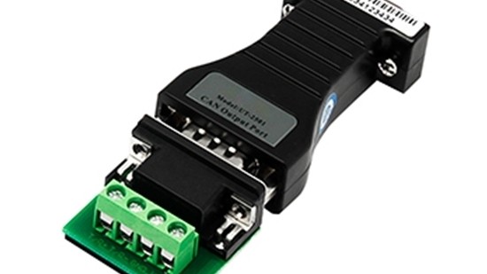
The Controller Area Network (CAN bus) is a robust, de facto standard for in-vehicle and industrial automation communications. However, system integration often encounters challenges due to protocol variations and physical layer disparities. CAN Bus Converters are critical interface devices designed to resolve these incompatibilities, ensuring seamless data exchange across heterogeneous network segments. This article explores the operational principles, primary functions, and key applications of these essential components.
1. The Need for Conversion in a CAN Ecosystem
A standard CAN network operates on a multi-master, broadcast-based principle with a differential two-wire physical layer (CAN_H and CAN_L). While this design is inherently robust, real-world systems are rarely homogeneous. Incompatibilities arise in two primary domains:
Protocol Level: The higher-layer protocols running on top of the basic CAN data link layer, such as CANopen, SAE J1939, or DeviceNet, have distinct message identifiers, data object dictionaries, and communication mechanisms. A simple J1939 message is not natively understood by a CANopen node.
Physical Layer: Variations in signaling voltage levels, baud rates, and connector types can prevent direct connection. For instance, a single-wire CAN (SWC) module cannot communicate directly with a standard high-speed CAN (HS-CAN) network. Furthermore, electrically isolating a noisy sub-network from a sensitive main network is often a necessity.
CAN Bus Converters are specialized gateways engineered to address these specific points of failure.
2. Core Functions and Operational Principles
A CAN Bus Converter acts as an intelligent bridge, performing one or more of the following critical functions:
2.1. Protocol Conversion and Gateway Functionality
This is the most common and sophisticated role. The converter operates as a dual-port device with independent CAN controllers. Its operational workflow is as follows:
1. Message Reception:** The device listens to all traffic on CAN Bus A (e.g., a J1939 network).
2. Filtering and Parsing: It employs user-defined rules to filter relevant messages (e.g., only Engine RPM and Vehicle Speed). Using knowledge of the source protocol (J1939), it parses the raw CAN data to extract the actual parameter values.
3. Repackaging and Transmission: The extracted values are then repackaged into the frame format and identifier structure of the destination protocol (e.g., CANopen). Finally, it transmits the newly constructed message onto CAN Bus B.
This process allows a J1939 engine control unit (ECU) to provide speed data to a CANopen-based industrial display, despite the two protocols being fundamentally different.
2.2. Physical Layer Adaptation
Converters can bridge different CAN physical layers:
HS-CAN to LS-CAN/Low-Speed Fault-Tolerant CAN: Adapting between the high-speed (up to 1 Mbps) and fault-tolerant (up to 125 kbps) variants common in automotive body electronics.
Dual-Wire to Single-Wire CAN (SWC): Enabling communication between standard CAN networks and GM's single-wire implementations.
Baud Rate Translation: Connecting network segments operating at different speeds (e.g., a 500 kbps powertrain network to a 250 kbps infotainment network).
Galvanic Isolation: Incorporating isolation barriers (e.g., opto-isolators or magnetic isolation) to break ground loops, suppress electrical noise, and protect sensitive components from voltage transients, which is crucial in industrial environments.
2.3. Data Logging and Monitoring
Many advanced converters include auxiliary functions, acting as a network sniffer. They can log raw CAN traffic, specific messages, or error frames for diagnostic purposes, providing valuable insights during system development and troubleshooting.
3. Key Applications
The application of CAN Bus Converters is vast and cross-industrial:
Automotive Engineering and Prototyping: Integrating new ECUs or data acquisition systems into a vehicle's existing network without altering the OEM network.
Heavy-Duty and Off-Highway Vehicles: Bridging between the standard J1939 networks used for propulsion and proprietary or CANopen-based networks for auxiliary equipment (e.g., crane controllers, harvesters).
Industrial Automation: Connecting industrial machinery using DeviceNet or CANopen to a central management system or to other fieldbus networks like PROFIBUS or Modbus TCP/IP (in more complex gateways).
Marine and Aerospace: Facilitating communication between different avionics or vessel management subsystems that utilize specialized CAN-based protocols.
Research & Development: Enabling prototype systems to interface with commercial off-the-shelf (COTS) components that use different CAN flavors.
4. Critical Selection Criteria
When specifying a CAN Bus Converter, engineers must consider:
Supported Protocols: Ensure the device explicitly supports the required source and destination protocols.
Configuration Flexibility: The availability of user-friendly software tools to define message filtering, mapping, and conversion rules is paramount.
Performance Metrics: Pay attention to the maximum data throughput and message latency to ensure the converter does not become a bottleneck.
Isolation Rating: For harsh electrical environments, a high isolation voltage (e.g., 1kV or 2.5kV) is essential.
Form Factor and Environmental Specifications: The device must be suitable for its intended operating environment (temperature, vibration, humidity).
5. Conclusion
CAN Bus Converters are far more than simple signal translators; they are strategic enablers of system integration and interoperability. By seamlessly bridging protocol and physical layer gaps, they extend the lifecycle of existing assets, simplify the development of complex heterogeneous systems, and enhance the overall robustness of networked electronic architectures. As CAN technology continues to evolve, particularly with the advent of CAN FD (Flexible Data-Rate), the role of these intelligent converters will only become more critical in the engineering landscape.

4 Comment(s)
1
1
1
1
1
1
1
1
1
1
1
1
1
1
Leave a comment